Small Where It Matters: Compact Separated-Geometry Lasers
Small Where It Matters
A practical guide to separated-geometry lasers for systems where space is tight at the point of emission.
Compact does not always mean small everywhere
In many instruments, the strictest mechanical constraint is not the laser system’s total volume. It is the space available where the beam must originate.
A laser may need to fit beside a camera, inside a probe, on a moving assembly, or deep within a densely populated optical system. There may be adequate space elsewhere for electronics, but only a few millimeters near the optical axis.
A conventional self-contained module places the diode, optics, driver, connectors, and supporting hardware in one enclosure. Separated geometry divides those functions so that only the optical head must occupy the point-of-emission envelope.
The better starting question: How much diameter and length are available where the beam must originate?
Where a smaller optical head can open design space
Life sciences
Microscopy, fluorescence, bioanalysis, diagnostic equipment, and compact probes.
Machine vision
Inspection heads, scanners, alignment systems, robotic tools, and production fixtures.
Precision instruments
Spectroscopy, semiconductor inspection, metrology, sensing, and analytical systems.
Aerospace & defense
EO/IR payloads, gimbaled sensors, autonomous platforms, rangefinding, tracking, and communications.
Compact optical head
Places the laser diode and beam-forming optics at the point of emission.
Remote driver
Moves current regulation and control to a location with more room for power, mounting, and thermal management.
Strategic placement for aerospace and defense systems
Separated geometry can support size, weight, and power objectives by allowing the optical head and electronics to occupy different locations within the platform.
Size
Fit the emission head into a crowded payload while placing the driver where suitable board space is available.
Weight
Move driver mass away from a gimbal, scanner, or articulated mechanism where moving mass and inertia matter.
Power & heat
Place the electronics near platform power and a suitable thermal path, away from sensitive optics or detectors.
Separated geometry redistributes system volume, heat, and mass; it does not eliminate them. Product-level suitability depends on the selected configuration and the program’s environmental and qualification requirements.
Three CW head sizes—and two paths beyond basic CW
Choose the smallest configuration that satisfies the diode, wavelength, power, beam, thermal, and control requirements.
View the separated-geometry family
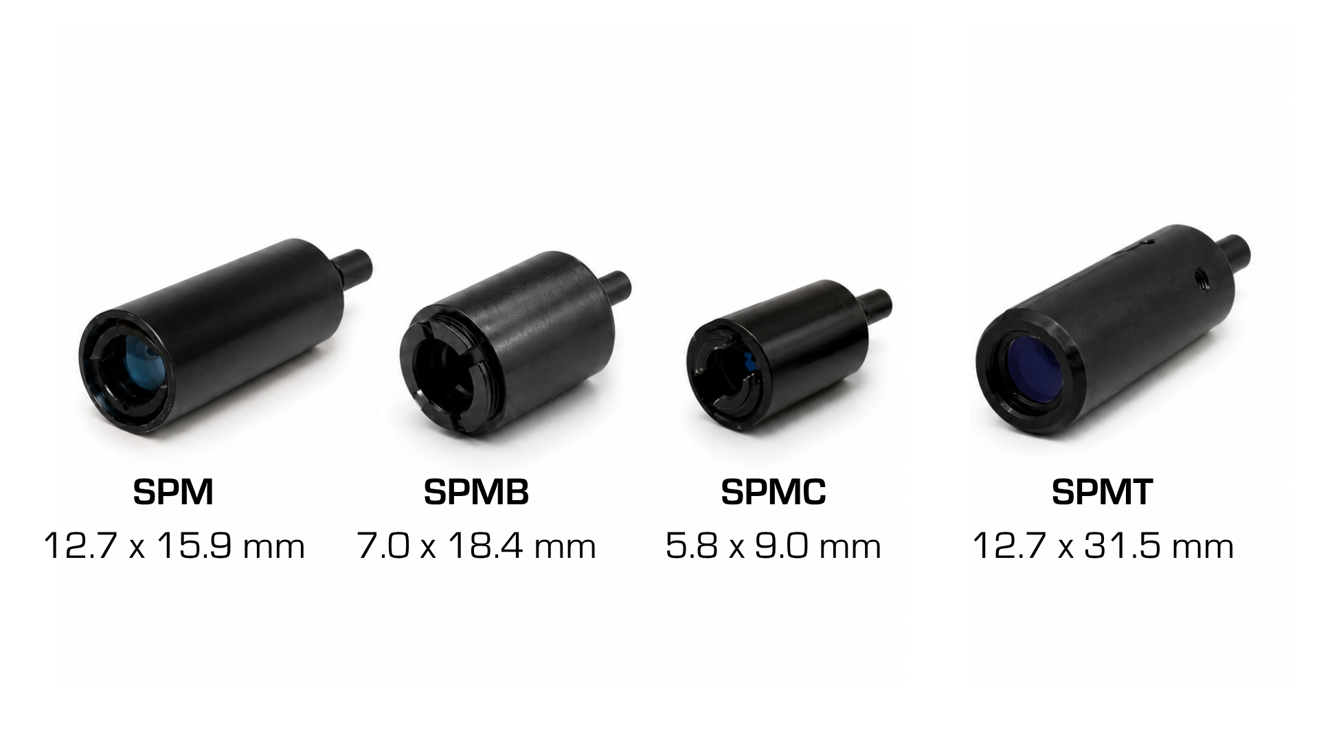
SPMC
Ø5.8 × 9.0 mm headPTI’s smallest standard separated-geometry head, built around 5.6 mm laser-diode packages for applications where diameter is the dominant constraint.
- Operating modeCW
- Diode package5.6 mm
- Family wavelength range375–1600 nm

SPMB
Ø7.0 × 18.4 mm headA compact CW head using 5.6 mm laser-diode packages when the application has slightly more installation space.
- Operating modeCW
- Diode package5.6 mm
- Family wavelength range375–1600 nm

SPM
Ø12.7 × 15.9 mm headThe most flexible standard SPM head, with support for both 5.6 mm and 9 mm laser-diode packages.
- Operating modeCW
- Diode packages5.6 mm & 9 mm
- Family wavelength range375–1600 nm

SPMT
Ø12.7 × 31.5 mm headSeparated geometry for applications that also require electronic beam switching or digital TTL modulation.
- Operating modeDigital modulation
- Modulation rangeCW to 20 MHz
- Typical operating voltage5 VDC
IQ separated geometry
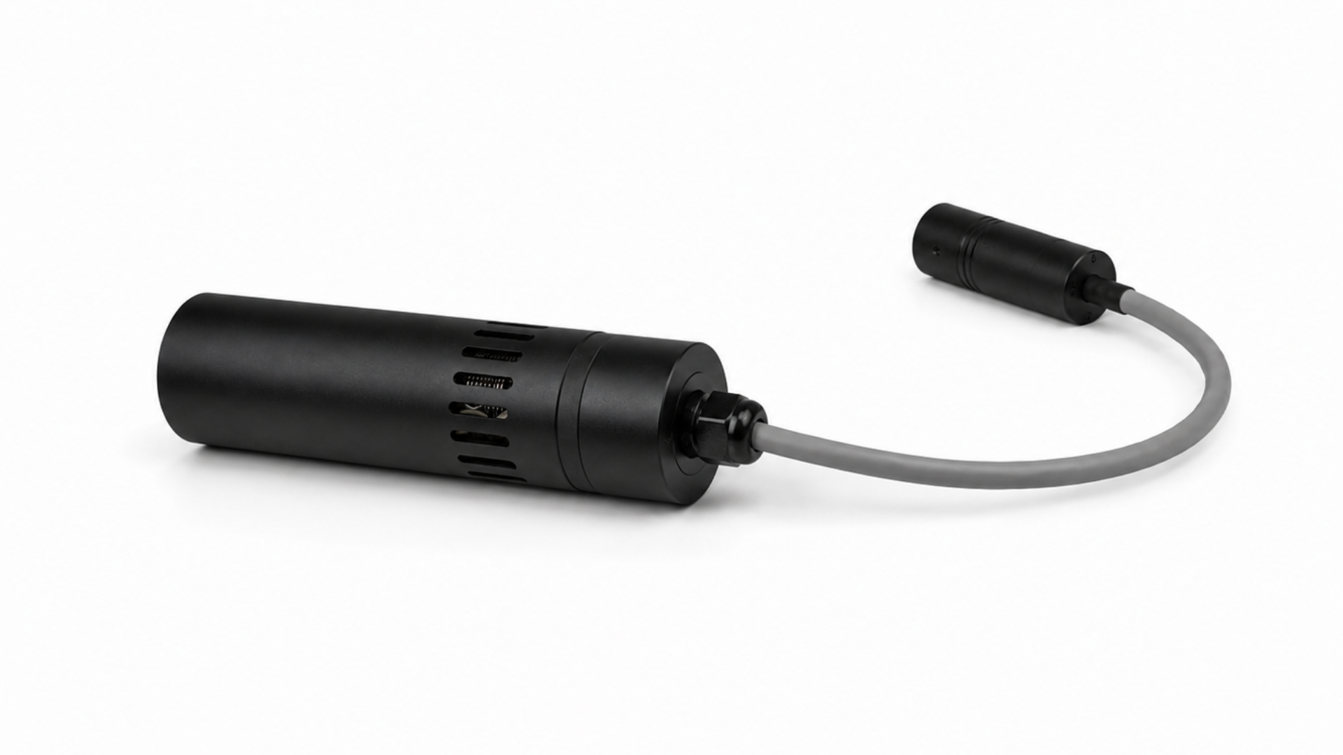
Ø19.1 × 51.8 mm headFor demanding applications where temperature, wavelength, output-power stability, and optical quality take priority over minimum head diameter.
- IQ headTEC-equipped
- Compatible diode package9 mm
- Published IQ1-SG pathsCW, analog & digital
- Remote electronicsØ38.0 × 133.5 mm
Which published options fit your available space?
Enter the maximum allowable optical-head diameter and length, then choose the required control type. This dimensional screen does not determine wavelength, power, optical, thermal, or environmental feasibility.
Plan the remote-driver envelope
Compare maximum package size, L × W × H. Dimensions exclude the 12-inch wire leads.
A dimensional match is not a product recommendation. Connectors, cables, mounting features, bend radius, and service clearances may require additional space. PTI must confirm the complete configuration.
The driver is part of the packaging solution
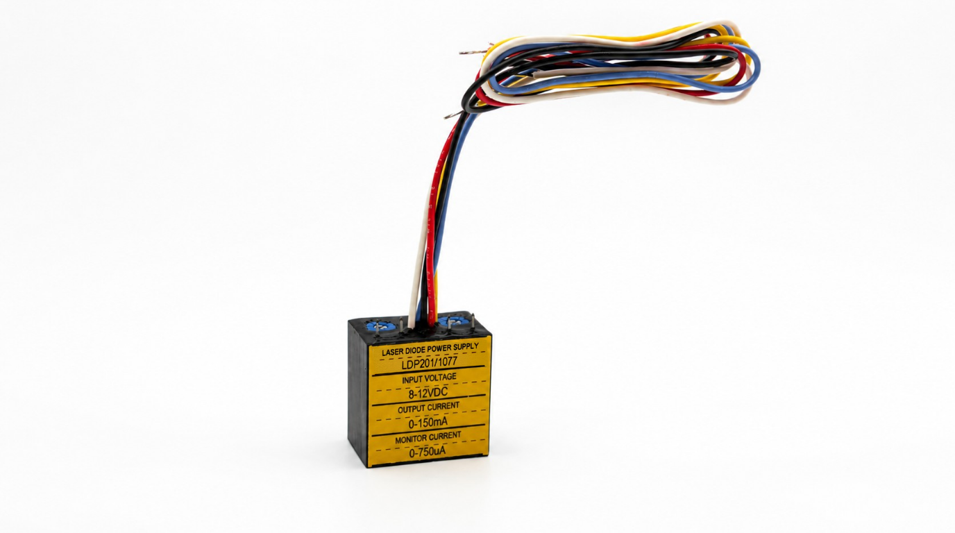
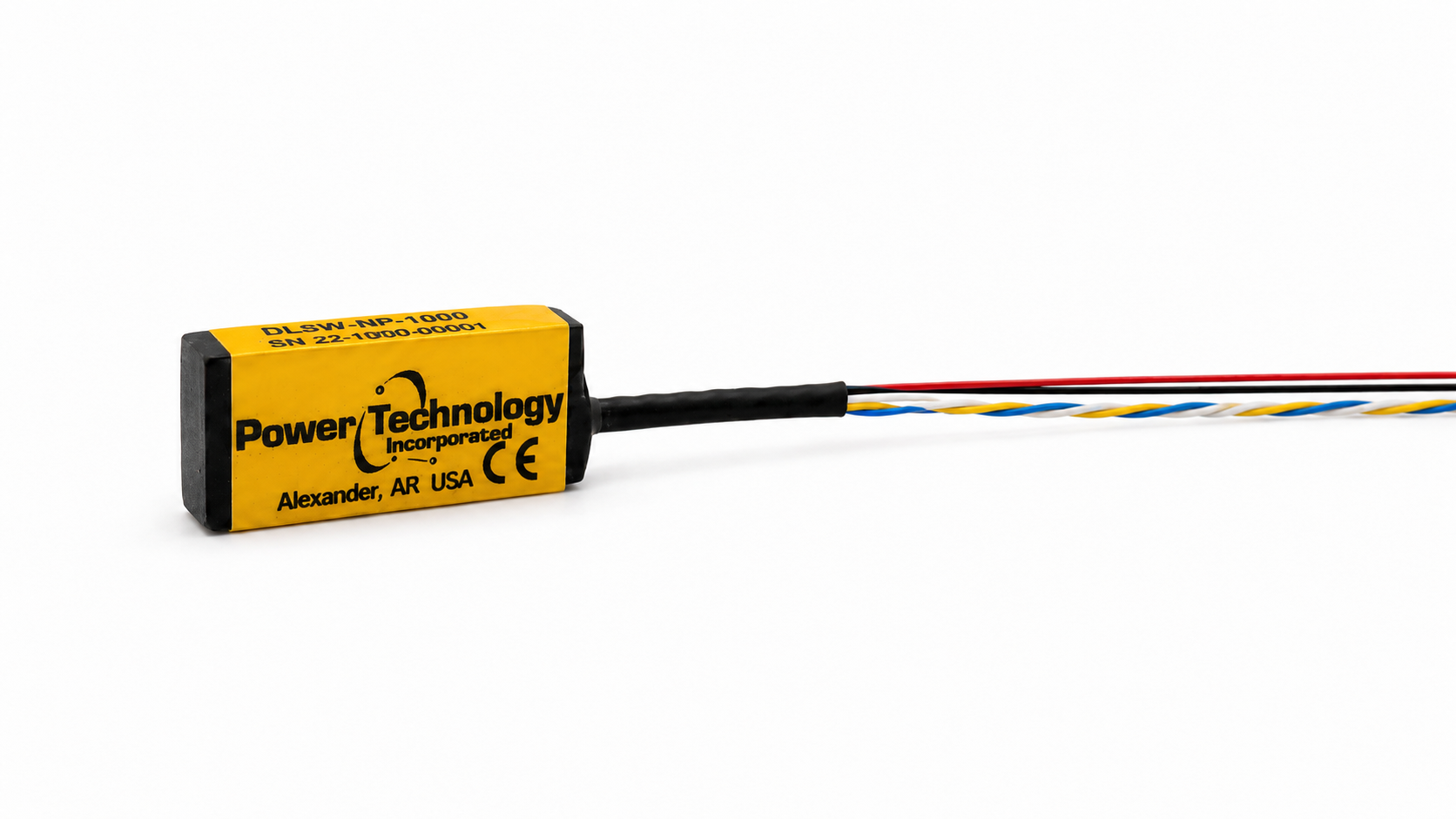
Driver selection depends on the laser diode and its electrical configuration. PTI offers compact LDP driver options for integration with separated-geometry laser heads.
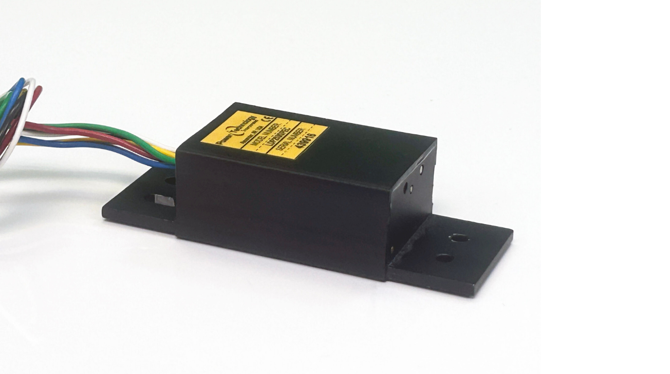
Design the head, cable, and driver as one system
The remote electronics can be positioned where board space, power distribution, thermal management, grounding, and service access are more favorable.
The package envelopes above are shown as length × width × height and exclude the 12-inch wire leads. The LDP-253 envelope includes its aluminum mounting bracket. Driver selection depends on the laser diode, polarity, monitor-photodiode arrangement, operating current, supply voltage, and control mode.
Benefits and engineering tradeoffs
Potential benefits
- Smaller package at the point of emission
- Greater freedom in optical and mechanical layout
- Driver heat located away from sensitive optics
- Lower mass on moving assemblies
- Remote access to controls and monitoring
- Independent head and electronics mounting
Design considerations
- The remote driver still needs space and thermal management
- Cables require routing and strain relief
- Cable forces can affect pointing stability
- Smaller heads can limit diode and optical choices
- Interconnect design matters for noise and modulation
- Sealing and ruggedization cover multiple assemblies
When a standard head does not fit
Physical diameter is only one constraint. An application may also require a shorter head, an application-specific focus, a particular cable exit, or custom mounting features.
PTI publishes standalone laser heads and collimators in additional configurations. Custom feasibility depends on the diode package, wavelength, output power, optics, heat load, cable design, operating environment, and production quantity.
Explore laser heads and collimators →Information to define first
- Maximum head diameter
- Maximum head length
- Wavelength and tolerance
- Optical output power
- Beam shape and focus
- Working distance
- CW or modulation
- Available supply voltage
- Cable length and route
- Operating temperature
- Shock and vibration
- Environmental sealing
Bring PTI the envelope and the optical requirements
Those requirements determine whether the right solution is SPMC, SPMB, SPM, SPMT, IQ separated geometry, or a custom head-and-driver assembly.